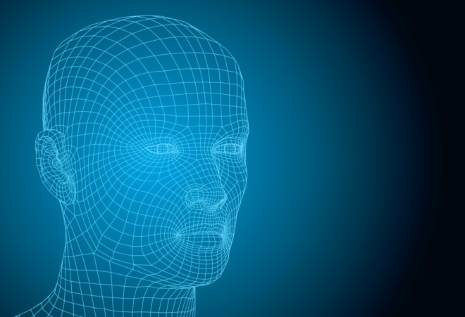
Identifying the source within the brain from which an EEG signal element originates is a complex problem that requires a model of the head and the tissues, the bone and skin, that lie between the brain and the scalp.
Source localization has been one of the primary goals of solving the inverse problem in EEG. What this means is identifying where in the brain a particular type of activity originates based on the surface EEG recording. This is particularly useful for something like epilepsy where you might want to figure out where a seizure is being initiated. However, it may also be useful to understand from where different stimulus responses come from.
see related post What Does the EEG Signal Measure?
At this point, it is important to recall a famous quote attributed to statistician George Box – All models are wrong but some are useful! In the previous post we discussed some of the major assumptions used to construct these models. Here we discuss the basics of how the models are constructed.
Identifying the source of an EEG signal requires three things: a source model, a head model and EEG data.
The Source Model
A source model simply tells us the three-dimensional positions (i.e., the xyz co-ordinates) of dipoles on the cortical surface. This is also sometimes referred to as source space. Generally it is assumed that EEG signals are generated by sources that can be approximated as dipoles (see previous blog post for a discussion of the source model and its assumptions)
The Head Model
Having defined the positions of the sources, we then need to describe how the electric currents from these sources will flow through the head and finally end up as EEG measurements on the scalp surface. This depends on two factors – 1) The geometry of the head and 2) The conductivity of various tissues in the head.
 Image taken from [2]
The geometry of the head can be obtained by structural magnetic resonance imaging (MRI) and there is a wide literature available on conductivity values for the various tissues. (Although skull conductivity is the biggest unknown – see previous post for more details). Assuming the conductivity values are known, or at least that the assumptions are reasonable, the more difficult problem is describing the flow of current through the complex geometry of the human head. This is a ‘forward problem’ that is not trivial.
Numerical techniques like finite element method (FEM) or boundary element method (BEM) are typically used for this purpose, which can be thought of solving this complex problem by dividing the geometry into small elements and solving the problem in each of these elements and finally combining all these tiny pieces of solutions into a global solution. This solution simply contains values of electric potential generated due to the dipoles at every point in every tissue in the head. The output is a matrix that contains values of electric potential generated due to the dipoles at every point in every tissue in the head. A toolkit for this is provided in www.sccn.ucsd.edu/wiki/NFT
Coregistration
An important aspect that has to be considered in building the head model is the coregistration of the EEG electrode locations with the head model. Note that the head model is constructed from the MRI image (of the subject) which lives in a different 3D coordinate system than the EEG electrodes which are simply on the surface of the scalp. Thus, it is necessary to align the EEG electrode locations to the subject’s MRI so that they are in the common coordinate system, before solving for electric potentials as described above. This procedure is done using fiducial markers, which are known anatomical locations (blue dots) as reference. The red dots below are the EEG electrodes.
 Image taken from [3]
The Model
Now we can model the measured EEG data as
y = Lq + n
Where, q is unknown the time-course of the unknown dipole strength, r is the dipole location the matrix L captures how currents from the dipoles are transformed into electric potential recorded at EEG sensors and n is the measurement noise, that can be for example estimated from baseline recordings in task-based experiments.
So the aim now is to estimate q given L, y and n!
Sources of Error
Aside from the unknowns in even the accepted assumptions (see The Inverse Problem in EEG – Assumptions and Pitfalls), there are many factors that can affect the solution to an EEG inverse problem, and consequently the source localization. One such important factor is the accuracy of the head model. What level of accuracy and realism will render a head model to be useful is debatable. One can construct a detailed head model as shown above with six tissues, but in principle a 4-layered model including brain, skull, CSF and skin should already give decent results [4,5] and thus the gain by having a detailed six-layer model could be marginal. Also, a recent study suggests that even a three-layered head model with decreased skull conductivity to compensate for the omission of CSF should suffice [6]. These aspects are quite important to take into consideration as building a detailed head model involves recognizing different tissues from the MRI, which is not trivial either in effort or time!
References
[1] http://www.scholarpedia.org/article/File:Source_localization_invforw.jpg
[2] Cho, Jae-Hyun, et al. “Influence of the head model on EEG and MEG source connectivity analyses.” Neuroimage 110 (2015): 60-77.
[3] http://www.besa.de/products/besa-mri/features/coregistration/
[4] Vorwerk, Johannes, et al. “A guideline for head volume conductor modeling in EEG and MEG.” NeuroImage 100 (2014): 590-607.
[5] Acar, Zeynep Akalin, and Scott Makeig. “Effects of forward model errors on EEG source localization.” Brain topography26.3 (2013): 378-396
[6] Stenroos, Matti, and Aapo Nummenmaa. “Incorporating and compensating cerebrospinal fluid in surface-based forward models of magneto-and electroencephalography.” PloS one11.7 (2016): e0159595.

